 Skip to content


YesWelder MP200 5-in-1 welder & cutter User Guide
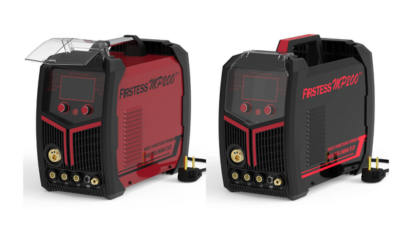
The YesWelder FIRSTESS MP200 is a portable, multi-process welder capable of performing the following processes:
- MIG welding (GMAW - Gas metal arc welding)
- Flux-cored welding - (FCAW - Flux-cored arc welding)
- DC TIG welding (GTAW - Gas tungsten arc welding)
- Stick welding (SMAW - Shielded metal arc welding)
- Plasma cutting
This guide will teach you how to set up everything for each welding process, from the necessary physical connections to the settings on the digital display. We will also share some helpful welding/cutting tips for a successful welding experience, but let's start with a quick safety overview.
To help find the topic you are looking for, here is a quick table of contents. We advise that you first read the safety and the general overview of the welder before jumping to any other part of the article and before you start working on exciting projects.
Welding And Plasma Cutting Safety
This article provides a general outlook on welding and cutting safety measures. You should continually educate yourself further and work on hazard prevention.
When performing any of the MP200 included welding processes be mindful of arc flash, radiation, fire hazards, electrocution, pressurized gas cylinders, physical injury, and welding fumes.
Never weld or cut if you are feeling unwell or if your state of awareness is down. Be mindful of the safety and power equipment you are working with. This includes angle grinders, table saws, presses, and other tools, not just welders.
You need a welding helmet, fire-resistant gloves, boots, jacket, and pants to weld safely. You will also need to wear safety glasses underneath your welding helmet. The MIG, Flux-core, and stick welding processes require heavier protective equipment than the TIG welding process because TIG doesn't produce as much spatter.
Take extra caution against water and moisture exposure when plasma cutting. The open-circuit voltage is higher when using plasma cutters than when welding, making it more of an electrocution hazard. Insulate yourself from the metal, and wear dry protective clothing when welding or cutting.
Be cautious of your pressurized gas cylinders like argon and CO2 shielding gases. Always keep them chained up to a secure place in the upright position and place the protective cap back on when they are not in use or during any transport.
Never keep anything flammable in the welding/cutting vicinity. Ensure that the work area doesn't have any crevices where the molten metal can fall and catch fire. Always check your work area after working for any smoldering pieces, smoke, or similar. Unplug all equipment before leaving the room. And most importantly, always have the appropriate fire extinguisher nearby.
Never weld in a closed room without good ventilation. Welding fumes are hazardous, cancerous, and lead to many illnesses. Always double-check the metal you are working with. Certain coatings like zinc (galvanized steel) and cadmium can cause severe health issues if inhaled. Such metal requires specialized PAPR equipment for safe welding.
Continuously learn and research welding safety. Welding is a beautiful hobby, trade, and a life passion of hundreds of thousands of people, but it can quickly become dangerous if hazard prevention steps are not implemented.
Overview of YesWelder MP200 5-in-1
The YesWelder MP200 is an inverter welder based on IGBT inverter technology. This makes the machine lightweight and allows for multiple advanced functions. Before we move on to a detailed explanation of how to set up the welder, let's explain some of its features and their purpose.
Synergic MIG welding automatically adjusts the voltage and wire feeding speed based on the amperage or the metal thickness selection. This makes the MIG welding process easier for beginners so that they don't have to manually adjust the wire feed speed and the voltage settings.
Another notable feature is the auto smart memory function. It allows you to store up to 10 different voltage and current settings for each welding type. You can recall the previously used settings at any time and save yourself the hassle of adjusting the process to your preferences.
If the welder ever gets overheated, it will activate its self-protection mechanism by shutting down in order to cool down, prolonging its life span. However, thanks to the advanced IGBT technology, the MP200 has a 60% duty cycle at 200A output when welding, and a 60% duty cycle at 40A when plasma cutting, giving you 6 out of 10 minutes intervals of working time.
This welder outputs DC current. So, it can weld mild steel and stainless steel. It cannot weld aluminum because it doesn't support AC TIG output or a spool gun. However, our YesWelder 250A AC/DC TIG and YesWelder 250A MIG are suitable for welding aluminum with TIG or MIG spool gun.
Like any arc welding machine, the MP200 requires you to correctly set up the polarities to initiate the arc in a closed electric circuit. This means that to run any of its five processes, you must connect the ground clamp to the metal and use the MIG/TIG/Stick/Plasma torch to close the circuit. It also requires a shielding gas for MIG and TIG processes and pressurized air for the plasma cutting process. So let's get started with an explanation of each.
How To Power the MP200
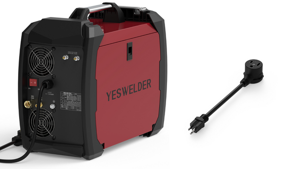
Regardless of the welding process, powering up the machine is done the same. The 220V input adapter is preinstalled with the power cord on the back of the YesWelder MP200. However, if you wish to use the welder with a 110V power supply, all you have to do is attach the 110V socket to the 220V plug conversion line supplied with the welder.
The back of the machine houses a red on/off button switch. After the welder is plugged into your 110V or 220V outlet, simply switch the button to on state, and the welder will turn on. This is followed by a YesWelder animation on display, and the menu will appear on it.
But before you power on the unit, you should attach everything that's necessary for the welding process you wish to run. So, let's get started by explaining the MIG setup first.
How To Set Up The MP200 For MIG Welding
To have a successful MIG welding experience, you will need to set up the shielding gas, polarity, wire feeding mechanism, and settings on the digital display. Before we go through each of these, let's take a look at MP200's specs for MIG.
Important parameters for MIG welding:
-
Output Current 110V: 20-160A, 220V: 20-200A
-
Wire feeding speed: Approx. 2.2 yd/min - 16.4 yd/min
-
Duty cycle: 60% at 200A
-
Voltage range: 15-24V
Shielding Gas For MIG Welding
To MIG weld, you need to use either 100% CO2, or the most popular mixture of 75% Argon (Ar) and 25% CO2. Using 100% CO2 is cheaper, but the arc is more erratic and produces more spatter. The 75% Ar gas provides the most stable arc, but it's more expensive and provides much better looking welds. Most home hobbyists use a 75/25 mixture, but you can also use different ratios and add helium or oxygen depending on your needs.
Argon/CO2 mixtures produce a hotter, more fluid weld pool, and support spray transfer. When MIG welding with this mixture, the penetration will be broader but less deep than with 100% CO2, making it a better choice for thin metal.
MIG welding mild steel with 100% argon gas is not recommended. Many home hobbyists who have TIG welded before may have a 100% Ar gas tank, but unfortunately, this is not a recommended gas for MIG. The arc will be erratic, have a horrible cutting out sound, and there will be a lot of soot around the weld.
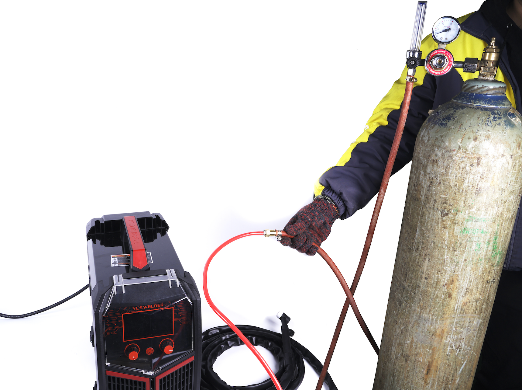
Attaching Your Gas Bottle to YesWelder MP200
Once you have purchased or rented your desired shielding gas cylinder, it's time to attach the gas flow regulator to it and connect it with the MP200.
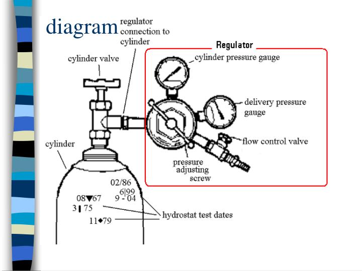
Image source: https://www.slideserve.com/jaden/chm-605-1221234
The gas regulator is not included with the MP200, so make sure you buy a proper regulator for the 75/25 mix. If you plan on using a 100% CO2 shielding gas, be aware that it requires a CO2 supporting regulator. Not all Ar/CO2 regulators can work with a 100% CO2 gas because of differences in inlets and the regulators' proclivity to freeze up with 100% CO2. We recommend using MP200 with a 75/25 mixture and a standard 75/25 gas regulator, because that way, you are unlikely to make a mistake.
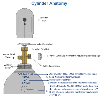
Image source: https://ehs.uci.edu/safety/pdfs/compressed-gas-reference-guide.pdf
Before attaching a gas regulator to the gas bottle, first remove the protective cap, and then crack the gas bottle for just a fraction of the second. This removes any hidden dust found in the vent of the bottle. Next, the regulator is attached by threading on the gas bottle valve by hand, and tightened by a wrench.
YesWelder MP200 includes an 8-foot gas hose with 5/8"-18 RH fitting. This gas hose is connected at the back of the unit, where the gas inlet is labeled "MIG GAS." The other end of the hose is connected to your gas regulator, which you have previously attached to the gas bottle. Make sure these connections are tight so that there is no gas leakage.
After everything is connected, you should slowly release the gas from the bottle. Don't open the valve quickly because if something is wrong with the regulator, it could come off, and the extreme pressure from the bottle could harm you. Pressurized gas cylinders are dangerous, and you should abide by all safety measures to prevent hazards.
Never move the gas bottle with a regulator on it. Instead, remove the regulator, screw back the protective cap, and only then move the bottle according to the OSHA safety standards.
Attaching the MIG Gun And The Ground Clamp
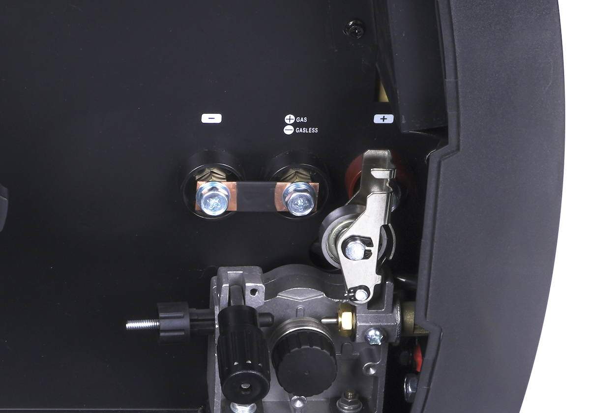
To successfully MIG weld, you have to use a DCEP polarity, which means that your welding electrode (MIG wire) is positive, and your ground clamp is negative. Inside the welder, there is a screw-on busbar connection to switch the polarity between positive and negative. You need to use the positive polarity for welding MIG, but when welding Flux core, you have to use negative. So if the unit on the inside is already connected with the busbar to the positive side, you don't have to do anything to weld MIG.
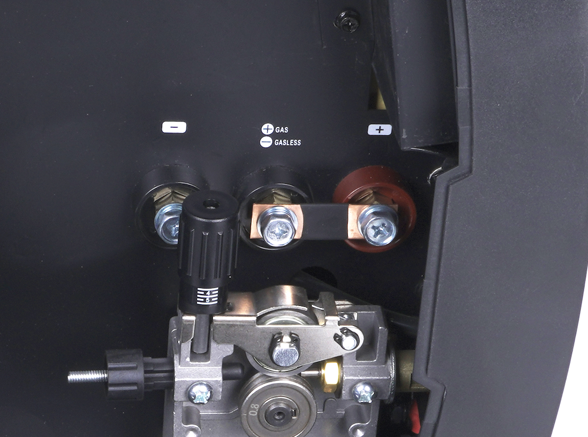
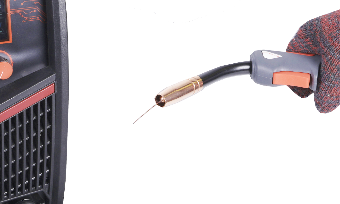
The MIG gun only connects one way to the large Euro MIG gun connector on the front of the machine. After you line up the connections, push the MIG gun connection into the unit and tighten the threaded collar to make an air-tight connection.
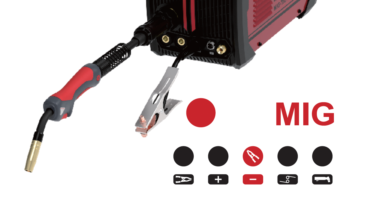
Since the MIG gun is DCEP when welding MIG, the ground clamp needs to be negative. So, take the ground clamp's Dinse connector, and connect it with the center port marked with the "minus" sign. The Dinse plugs work by pushing and twist-locking after aligning the lip on the brass plug to the socket on the welder.
Installing a Solid MIG Welding Wire In The Welder
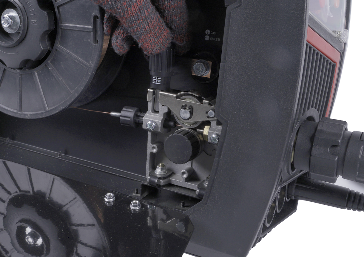
After the shielding gas and the MIG gun are set up, the wire feeder and the solid MIG wire spool are next to prepare. The wire feeder is located inside the unit. So, pull on the latch and open the side doors by pulling them downwards.
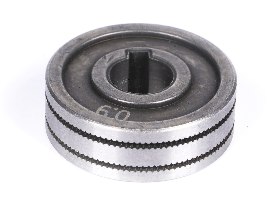
Installing The Appropriate Wire Drive Roller
The YesWelder MP200 comes with a .030" & .035" V-Groove and a .030" & .035" W-Groove rollers. The V-groove is used for solid MIG wire feeding, while the W-Groove is used for flux-cored wire. You will recognize the V-Groove roller by the smooth grooves, while the W-Groove has knurled grooves in it.
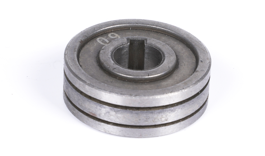
The entire wire feeding mechanism is located in the bottom right on the inside of the welder, and it's housed in a cast aluminum body. It consists of three main parts: a feed tensioner, idler arm, and a feed roller knob.
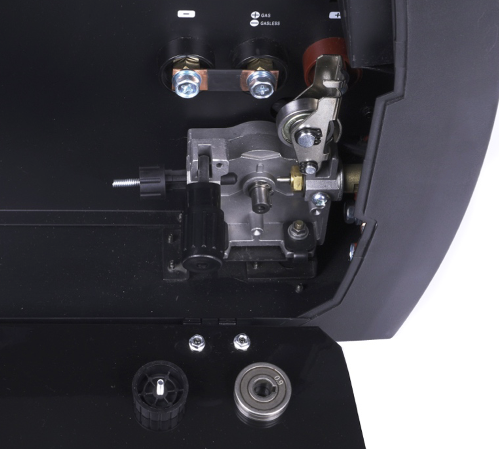
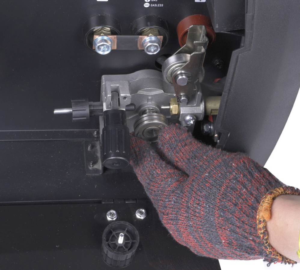
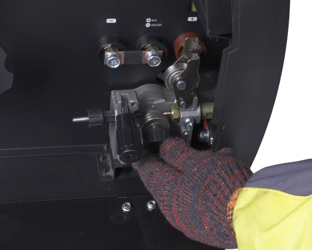
To install a V-Groove drive roller, you need to loosen the feed tensioner, pull it down, and as a result, the idler arm will move up on its own. Now your feed roller knob is accessible. Unthread the black plastic cap by hand, and remove/change the wire drive roller. For MIG, we want to use the V-Groove roller, so align it with the post on the shaft, thread the black plastic knob back on, and the appropriate wire roller is installed.
Installing The MIG Wire Spool
To install the MIG wire spool, first remove the big plastic spool knob/collar. Then place the spool of wire over the built-in adapter so that the pin on the adapter aligns with the hole on the MIG wire spool (all MIG wire spools have this hole).
The MIG wire spool should be installed to unwind counterclockwise, and feed the wire from under the spool.
Once the wire spool is in place, detach the end of the wire and firmly hold the wire not to unravel on its own by keeping tension on it. Next, cut off the end of the wire to have a clean, straight wire end. By holding the wire with one hand, push it through the first wire inlet liner, and all the way through so that it enters the MIG welding gun liner.
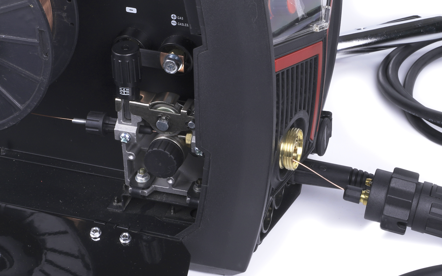
The idler arm also contains a built-in roller wheel that applies pressure on the welding wire from the feed tensioner. So, after the wire has entered the MIG gun, put the idler arm down, lift the tensioner up and increase the pressure of the tensioner by turning it.
Now you will need to remove the MIG gun's nozzle and the tip. Next, turn on the machine, enter the MIG mode, and pres-hold the left knob on the front panel. This will feed the wire through the lead to your MIG gun's tip. At this point, slide the tip over the wire, thread it back in, and put the nozzle back on.
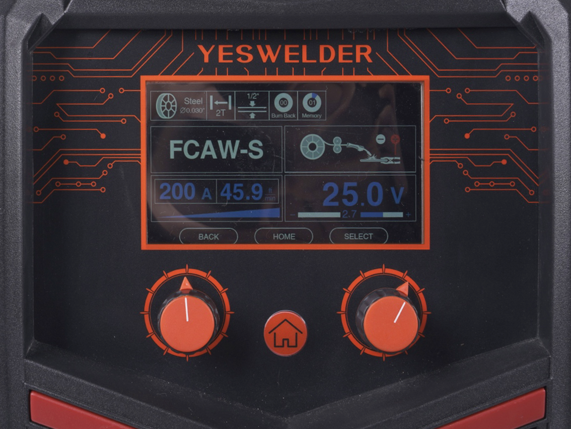
The MIG Welding Process Settings
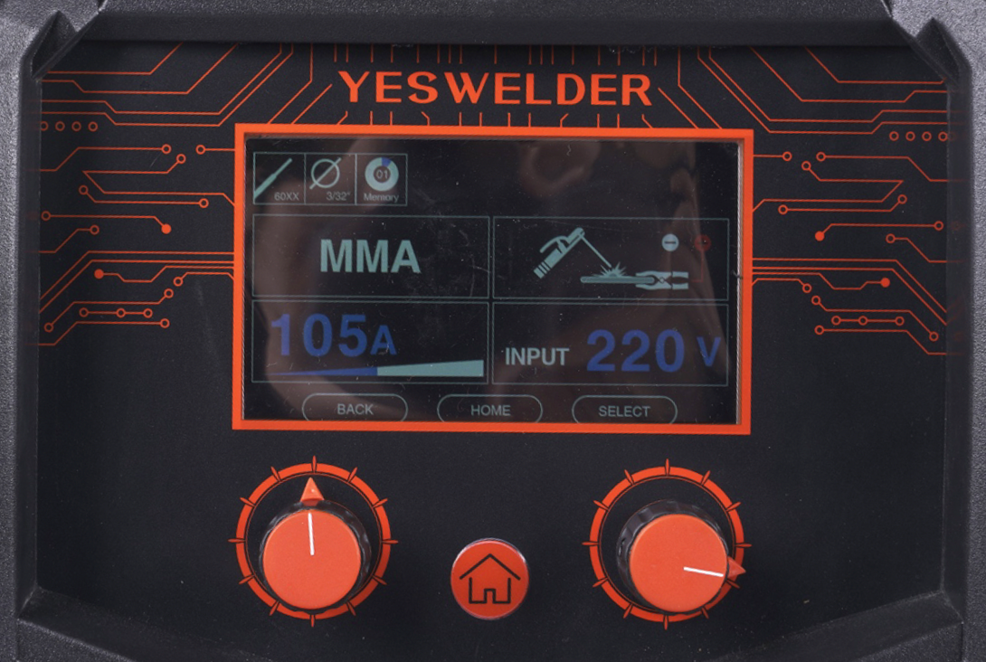
Upon entering the MIG welding mode in the main menu on display, you will see your current and voltage settings, the polarity, and the upper row with additional settings.
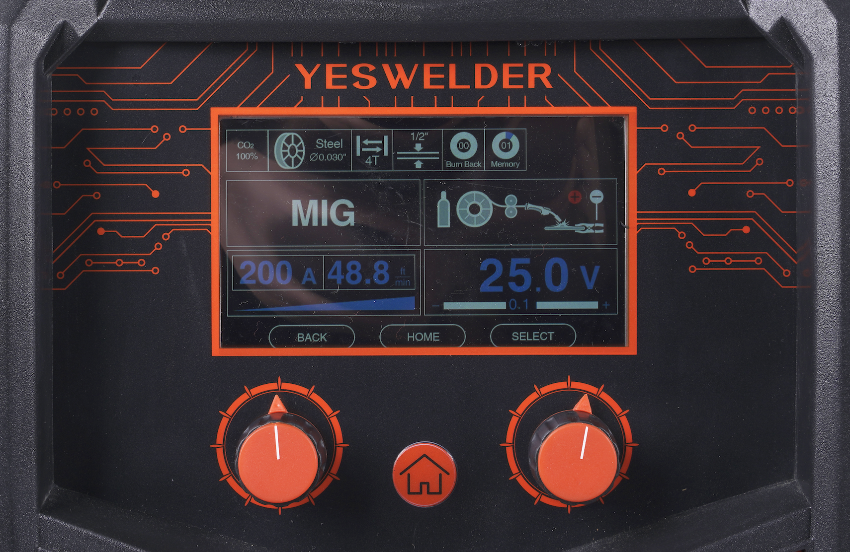
The left infinite adjustability knob modifies your amperage output, the wire feeding speed, and voltage as shown on display. The right knob adjusts the voltage value, allowing you to manually tune the desired settings.
Pressing the right knob acts as a "select" function, allowing you to enter the settings located on the top of the display. Here you can select the shielding gas, wire type (stainless, mild steel), wire size (0.030: or 0.035"), 2T/4T mode, metal thickness selection, burn-back setting, and memorizing your current setup.
The burn-back setting allows you to modify the time the wire is energized after releasing the trigger. So, if your wire is burning back to the tip, you can tune this value and adjust it to your style.
How To Set Up The MP200 For Flux-Cored Welding
The flux-cored welding process is similar to the MIG welding process, except that it doesn't use a shielding gas. Instead, the shielding action comes from the flux located inside the core of the wire.
To successfully perform flux-cored welding, you will need to use the correct polarity, install the flux-cored wire, and set the settings on display. So, let's go through each of these.
Attaching the MIG Gun And The Ground Clamp
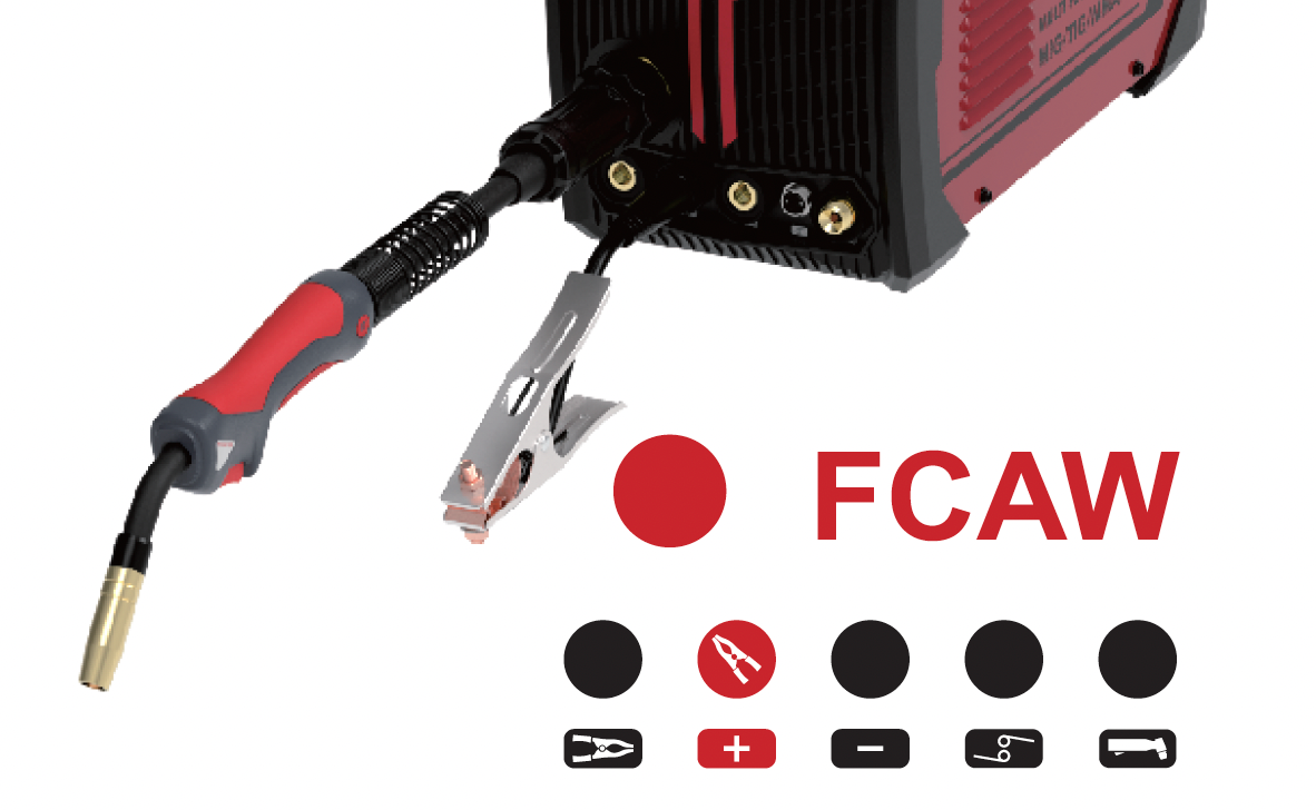
Unlike the MIG welding process, the FCAW requires the DCEN polarity. This means that the busbar on the inside of the welder needs to be reversed from positive to negative. To do this, unscrew the connection on the positive side marked red and with the "plus" above it, rotate the metal busbar to the negative, black side, marked with the "minus," and screw it in.
The FCAW process uses the same MIG gun as the GMAW, so the installation process is identical as described for the MIG process above. However, the ground clamp needs to be plugged in the positive port marked with the "plus" sign on the front of the machine.
Installing a Flux-Cored Welding Wire In The Welder
The flux-cored wire installation process is identical to the solid MIG wire installation process described earlier, with one crucial difference. Unlike solid wire, the flux-cored wire requires the W-Groove roller.
So, just as when setting up the MIG, loosen the feed tensioner and pull it downwards. This releases the idler arm and grants you access to the feed roller. Unthread the black cap, remove the V-Groove used for MIG, and install the W-Groove (knurled) roller for flux core wire.
Next, remove the big plastic spool knob/collar, and install the flux-core wire spool so that its hole aligns with the pin on the adapter.
Proceed by releasing the tip of the wire from the spool and cutting the end off while firmly holding the wire on the spool to prevent it from unraveling on its own. Push the freshly made tip into the wire feeding mechanism all the way through to enter the MIG gun. Afterward, put down the idler arm and lock it in with the feed tensioner.
Now you are ready to power up the machine. Choose the FCAW process in the menu, and press-hold the left knob to feed the wire through the liner and into the MIG gun.
The Flux-Cored Welding Process Settings
The menu settings for the FCAW welding process are completely the same as with the MIG welding process, except for the shielding gas setting because the flux-cored process doesn't need the protective gas.
The left knob modifies the amperage output, wire feeding speed, and voltage settings in synergy, while the right knob allows you to manually fine-tune the voltage settings. Pressing the right knob provides access to the flux-cored wire selection, 2T/4T mode, material thickness. burn-back, and the memory settings.
How To Set Up The MP200 For TIG Welding
To successfully perform a TIG welding process, you need to set up the shielding gas, polarity, TIG torch, and the settings on display. But before we explain each of these, let's look at MP200 specifications for TIG.
Important parameters for TIG welding:
-
DC TIG welding only
-
Lift start TIG
-
Output Current 110V: 20-160A, 220V: 20-200A
-
Duty cycle: 60% at 200A
-
Voltage range: 10.8-18V
Shielding Gas For TIG Welding
To TIG weld mild steel or stainless steel, you need to use a 100% argon shielding gas. You cannot use the 75/25 mixture with the CO2 typically used for MIG welding.
You can also use an argon/helium mixture for improved penetration and travel speed, but helium is more expensive, and so is the mixture.
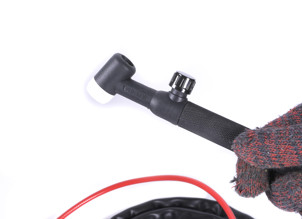
Attaching Your Gas Bottle to The TIG torch
Unlike the MIG welding process, the MP200 requires the shielding gas bottle to be connected directly to the supplied WP-17V TIG Torch.
The process of attaching the shielding gas regulator to the gas cylinder is completely the same as previously described for the MIG welding process. The difference is that instead of connecting the bottle-mounted gas regulator to the back of the MP200, you will connect it with the TIG torch.
The TIG lead has a built-in gas hose that connects to the regulator on the shielding gas. Take the end of this hose and thread it in the regulator manually, and then tighten it with a wrench to make a tight connection.
Before you start welding, you need to open the valve on the TIG torch to release the shielding gas. Make sure you keep the torch a few seconds over the completed weld to shield it as it cools down, and then tighten the valve to stop the gas flow.
Assembling the TIG Torch
Aside from the connection with the shielding gas, the TIG torch consumables must be assembled appropriately. This includes selecting and installing a ceramic cup, collet body, collet, tungsten, and the back cap.
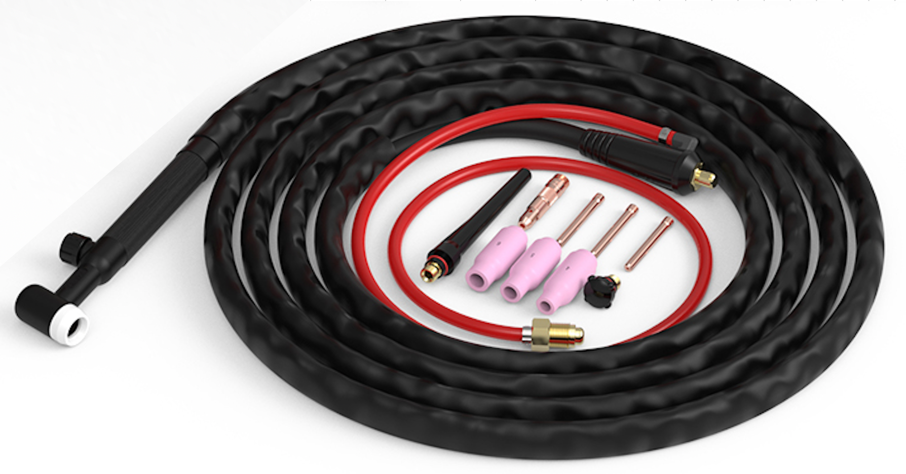
In short, the bare torch needs the back cap on the rear, and the collet body, collet, tungsten, and a ceramic cup on the front, and in that order.
The MP200 comes with two different back caps. The short one is used when you are welding in a tight space and need to limit the size of your torch, but it also limits the size of your tungsten. The long back cap lets you use the full length of your tungsten, so you don't have to cut it apart.
To assemble the front part of the TIG torch, select the appropriate size collet for your tungsten and slide it over the tungsten electrode so that the tip of the tungsten enters on the side of the two slits of the collet. Next, place the collet and the tungsten inside the collet body and thread the collet body to the TIG torch head. Before you tighten it with your hand, adjust the length of the protruding tungsten by sliding it back and forward.
After you set the desired tungsten electrode stick out, take the ceramic cup and thread it by hand over the collet body. The MP200 comes with different cup sizes. The size of the cup determines the amount of gas coverage you can have over the weld, but also the necessary rate of gas flow.
If you use a smaller cup size, you can save some gas, but this is possible only if the weld area is not large. For example, if you are welding a wide joint, you will need as much shielding gas as you can get. Additionally, small cup sizes are helpful if you want to reach a tight space and the larger cup just can't fit.
Tungsten Electrode Selection
There are many tungsten electrodes, which causes quite confusion with the TIG welding beginners. Tungsten electrodes are classified according to their principal oxide and its percentage of the total electrodes' mass.
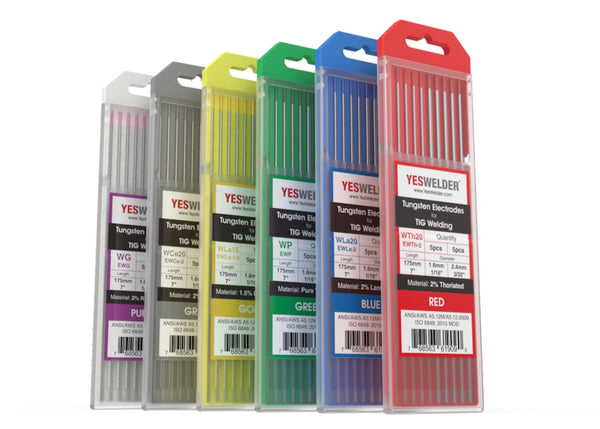
Commonly used tungsten electrodes are: pure tungsten, thoriated, lanthanated, ceriated, zirconated, and the rare earth mix tungsten electrodes. For DC TIG welding mild steel and stainless steel with the MP200, it's recommended to use the thoriated and ceriated tungsten electrodes. They handle steel welding well and work great with the DC TIG welding process.
The thoriated tungsten is radioactive, so you should take caution when grinding its tip and abide by the manufacturer's safety instructions. The ceriated tungsten is not radioactive, but it doesn't handle very high amperage, making it a good choice for welding thin sections.
Attaching the TIG Torch And The Ground Clamp
Once the shielding gas is connected to the gas bottle and the torch is assembled. You need to attach the TIG torch and the ground clamp to the welder with the correct polarity.
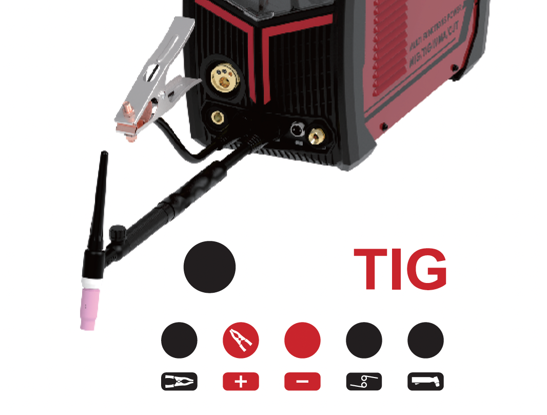
The TIG welding process is done with DCEN, meaning that the TIG torch needs to be plugged into the negative terminal marked with the "minus" sign, and the ground clamp is plugged into the positive terminal marked with the "plus" sign.
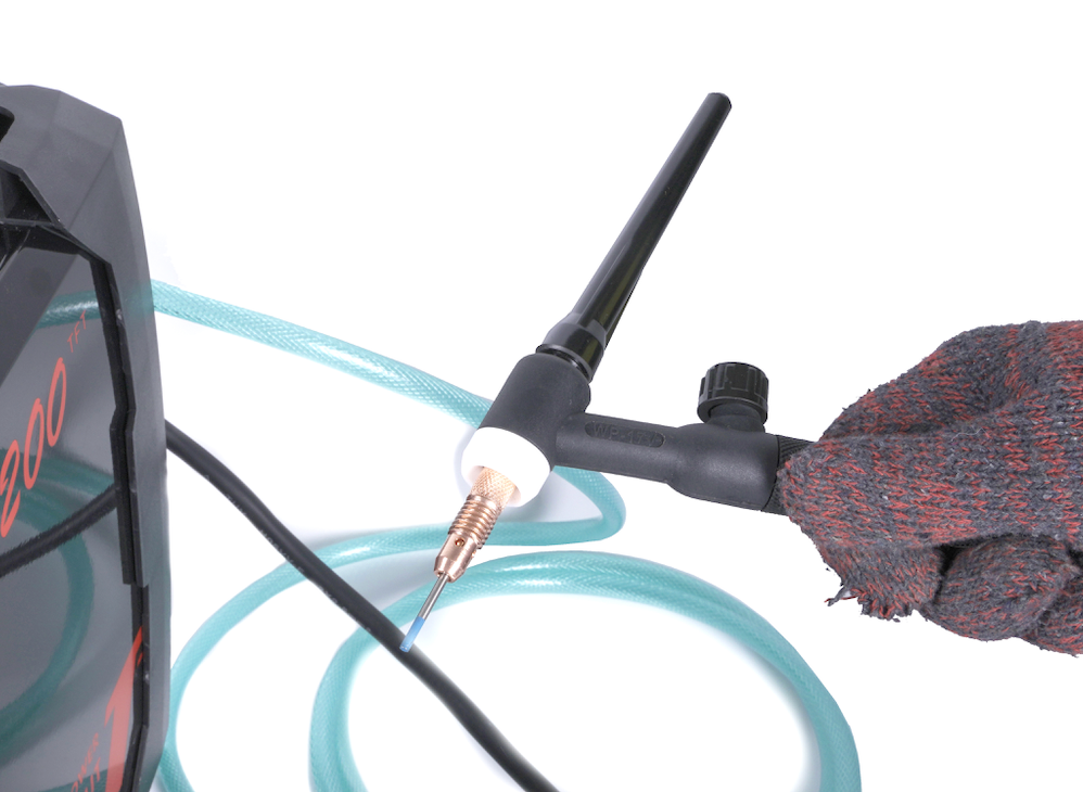
The Lift TIG Arc Start
The YesWelder Firstess MP200 supports a lift TIG arc start, which is a relatively clean process compared to the scratch start.
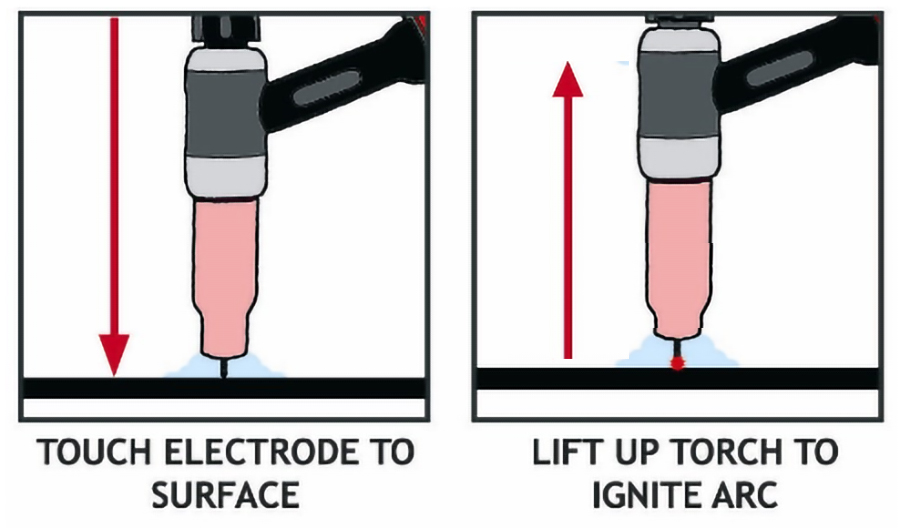
Image source: https://www.weldclass.com.au/blog/40-tig-welding-what-is-scratch-start-lift-arc-and-hf-ignition-
To initiate the arc, bring the tungsten electrode tip down to the metal piece to touch it lightly, and then quickly lift the torch upwards to draw the arc between the tungsten tip and the metal. Don't scratch the tungsten over the surface of the metal, it's unnecessary, damages the tungsten tip, and it can contaminate the weld with the residue from the tungsten electrode.
The TIG Welding Process Settings
Selecting the TIG welding process on the MP200's digital display allows you to start welding TIG, shows you the correct polarity for attaching the torch and ground clamp, and lets you modify the amperage output.
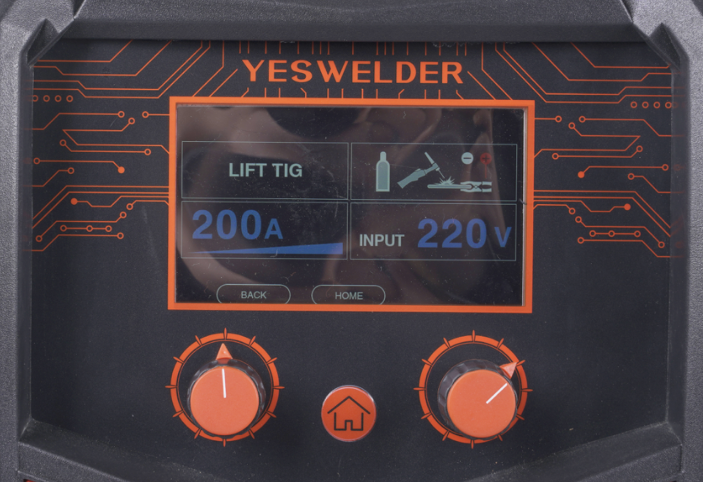
Rotating the left knob changes the welding amperage output in small increments. Fine-tuning the amperage helps you dial in the weld perfectly depending on the metal thickness and joint configuration.
How To Set Up The MP200 For Stick Welding
The stick welding process is quite different from the previously described welding methods, but it's the most effortless process to set up with the MP200. You need to attach the leads with the correct polarity, and set the settings on the digital display in the stick mode. But before we discuss these in detail, make sure you check the MP200's specifications for welding with the SMAW process.
Important parameters for Stick welding:
-
DC stick welding
-
Output Current 110V: 20-160A, 220V: 20-200A
-
Duty cycle: 60% at 200A
-
Voltage range: 20.8-28V
-
Supports all standard electrodes for mild steel like: E7018, E6011, and E6010
-
Maximum electrode diameter 110V: 1/8" (3.2mm), 220: 13/16" (5mm)
Connecting the Stick Electrode Holder And The Ground Clamp
The stick welding process works with the DCEP or DCEN polarity, and its selection is primarily influenced by the desired results and the stick electrode. The DCEP provides a more stable arc when stick welding, and achieves deeper penetration. Still, the DCEN is great when welding thinner materials or if you don't want to input maximum heat into the metal, like when performing surfacing welds.
Every electrode has a specified polarity it will work with. You can get this information from the stick electrode package, or by contacting the manufacturer. But typically, the polarities of common electrodes are as shown below:
-
E6010 - DCEP
-
E6011 - AC or DCEP
-
E6012 - AC or DCEN
-
E6013 - AC, DCEP or DCEN
-
E7015 - DCEP
-
E7016 - AC or DCEP
-
E7018 - AC or DCEP
To set your stick welding process in the DCEP mode, attach your electrode holder to the positive terminal marked with the "plus" sign, and your ground clamp to the negative terminal marked with the "minus" sign on the front of the MP200.
To set the stick welding in the DCEN mode, reverse the connections. The electrode holder is connected to the negative terminal, while the ground clamp to the positive.
Just like with the TIG, the SMAW leads have the Dinse connectors. So, just align the lip on the brass plug with the socket on the welder, twist and lock it in.
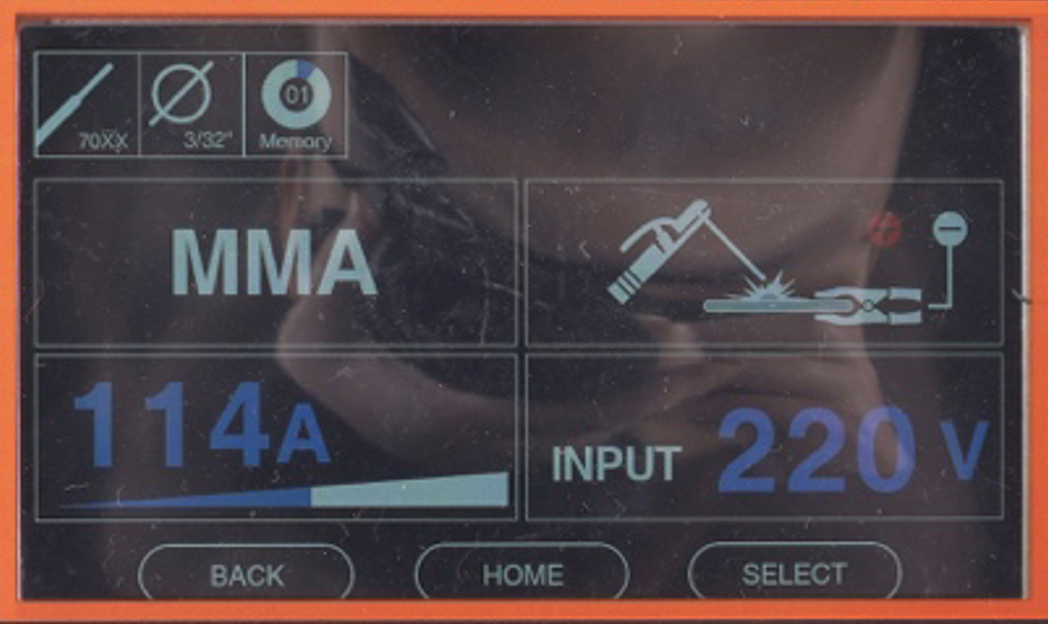
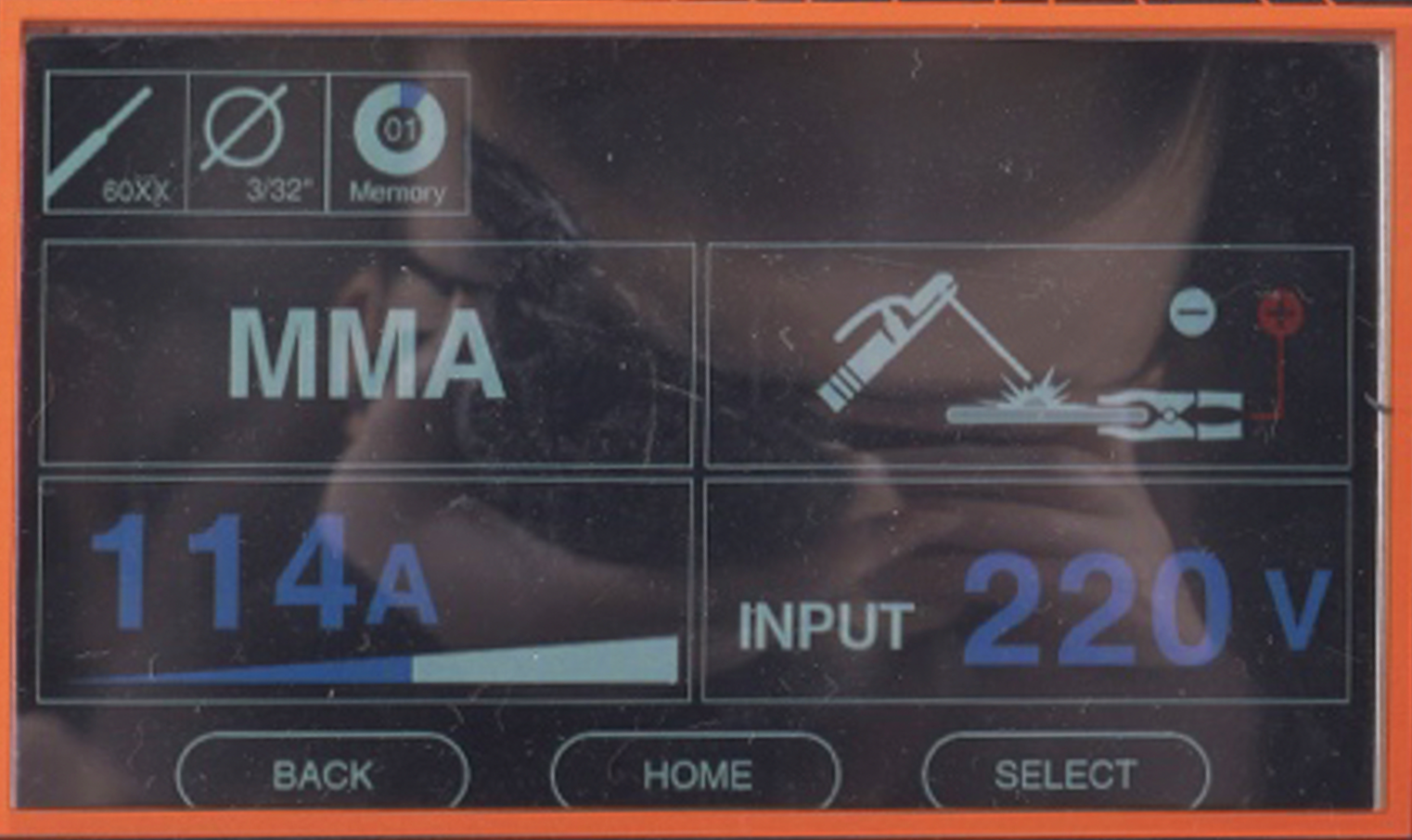
The Stick Welding Process Settings
The SMAW welding menu of the MP200 lets you select the 60 or 70 series welding electrodes and the electrode diameter. The electrode selection shows the required polarity on display, and you can modify the amperage output just like with the TIG by turning the left knob.
How To Set Up The MP200 For Plasma Cutting
Performing a plasma cutting process successfully requires properly setting the air filter, pressurized airflow, plasma torch, and plasma cutting settings. The plasma cutting specifications are below:
Important parameters for plasma cutting:
-
Output Current 110V: 20-30A, 220V: 20-40A
-
Duty cycle: 60% at 40A
-
Voltage range: 88-96V
-
Max clean cut 110V: 0.19" (5mm) at 30A, 220V: 0.27" (7mm) at 40A
-
Max severance cut 110V: 0.31" (8mm) at 30A, 220V: 0.5" (12.7mm) at 40A
-
Recomennded air pressure: 58-72 PSI
How To Set Up The Compressed Air Flow
Plasma cutting requires the use of an external air compressor. We recommend an air compressor with an output of 9-12CFM @ 78 PSI. Use only clean, dry, compressed air for plasma cutting. Never use oxygen, acetylene, carbon dioxide, combustible gases, or any other bottled gas because this can cause an explosion and serious injuries or death. The plasma cutter outputs high heat and can only be used with compressed air.
Before you connect your air compressor with the MP200, you need to assemble the air filter on the back of the machine.
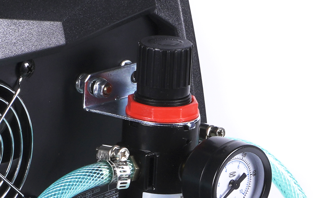
Installing the Air Filter (Oil-Water Separator)
The MP200 comes with an air filter. Its purpose is to separate the water from the air, which makes plasma arc better and conserves the life of the consumables. The copper consumables are exposed to severe heat, much higher than their melting point. If the moisture from the air enters the torch, the hydrogen and oxygen will erode consumables faster. The air filter traps the moisture from the air, and as a result, the purified air is supplied to the plasma cutting torch.
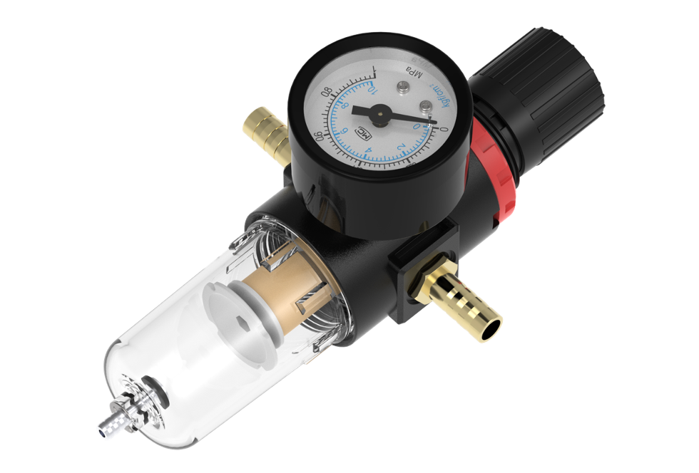
The air filter needs to be mounted at the back of the MP200, connected with the air compressor and the MP200 air inlet. The air from the compressor goes into the water separator (air-filter), gets filtered, and the purified air enters the MP200.
The arrow on the air filter points in the direction of the airflow. So, you need to thread the air compressor inlet connection and the brass barb for the air outlet according to the designated airflow. The inlet receives the air from the compressor and is the side where the flow begins, while the outlet provides it to the MP200 and the side where the air exits.
You also need to thread the pressure gauge on the front of the air filter. All three threaded fittings need to be wrapped with the supplied tape to make the air-tight connection.
Once all of the three elements are threaded and tightened with the wrench, it's time to hook the assembled air filter to the back of the machine.
In the package, you will see the bracket with a circular hole and a small lip on the front. Unscrew the two nuts located at the back of the welder above the wording "air filter installing place," and install this bracket with its bent lip facing downwards.
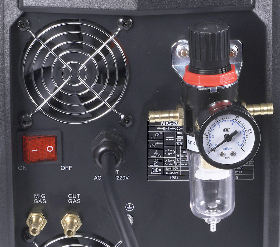
Next, take the assembled air filter and place it in the bracket from underneath so that the lip from the bracket matches the indentation on the regulator. Afterward, take the red plastic ring and install it from above on the threads of the regulator by tightening with a hand.
Connecting The Air Supply
After the air filter is assembled and installed, you need to connect the air compressor to the installed inlet on the regulator and use the supplied air hose to direct the airflow from the outlet to the air inlet valve at the back of the welder.
Take a supplied hose clamp and put it over the end of the supplied air hose, and slide the hose over the brass barb (air out). Tighten the hose clamp firmly with a wrench or a socket but not too tight to damage the hose.
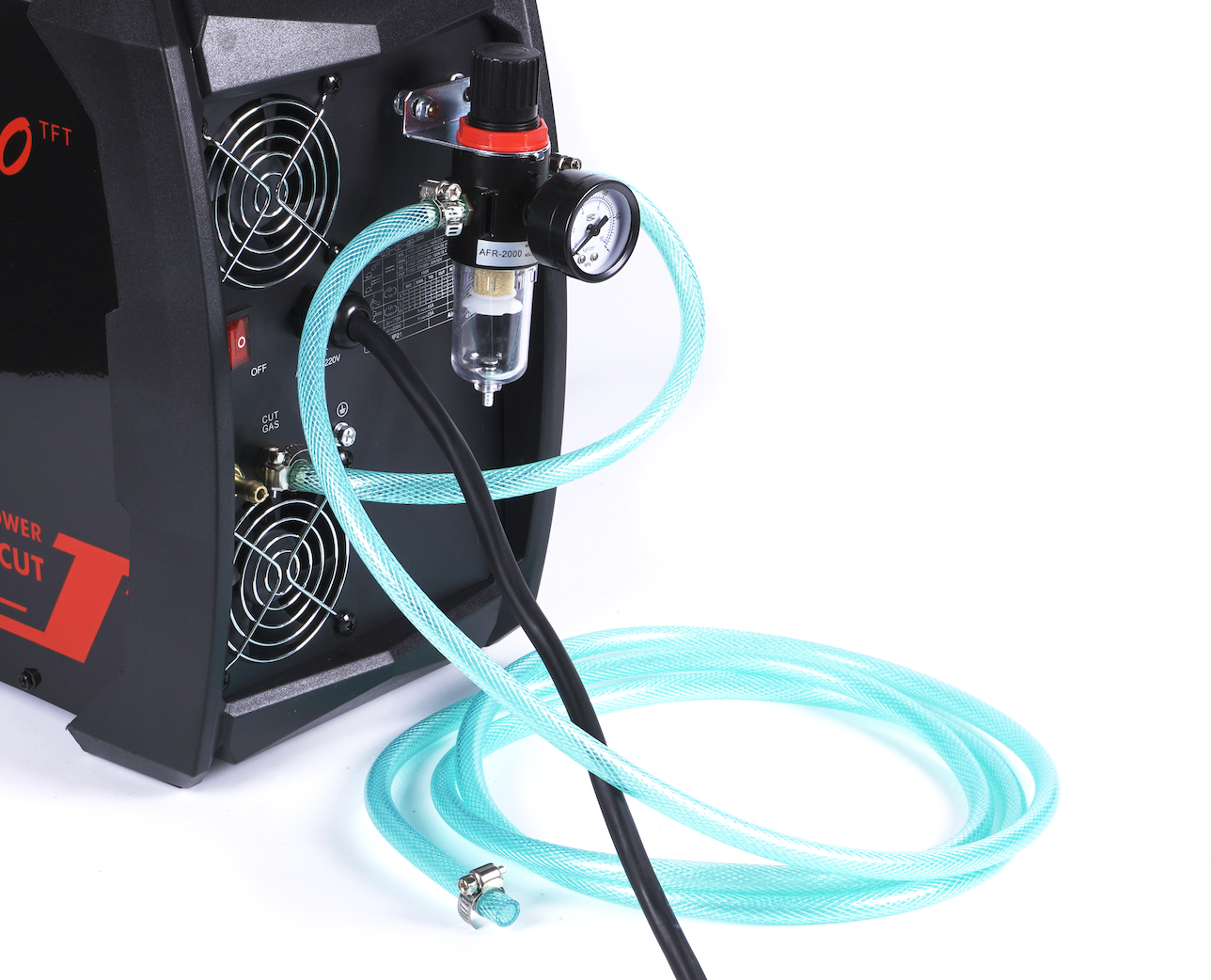
Repeat the same process with the other end of the air hose and the air inlet on the back of the welder with the wording "CUT GAS." Use the hose clamp and tighten everything firmly. Ensure that the hose is not kinked before you tighten connections on both sides.
Supplying The Air
Once you power up and get your air compressor ready according to its manufacturer's instructions, attach it to the air filter's inlet side.
Next, gently pull up the plastic knob on the top of the air filter until it clicks and elevates, rotate it clockwise to set the desired air pressure, and push it down to lock in place.
Assembling The Plasma Cutting Torch
The plasma cutting torch comes already assembled, but when replacing the consumables, you will need to disassemble the head and put it back together.
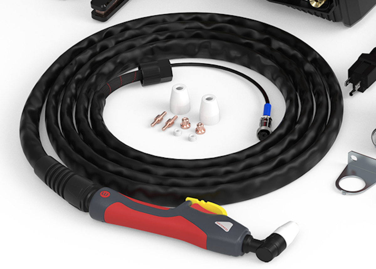
The torch head consists of a swirl ring, electrode, cutting tip, and a shielding cap. To put everything together, place the electrode inside the torch head and mount the swirl ring over the electrode. Next, place the cutting tip over the two and thread the shielding cap over everything to the threads on the outside of the torch head.
Connecting The Plasma Torch And The Ground Clamp
Connecting the plasma torch and the ground clamp is straightforward because they have dedicated sockets on the front of the machine. You don't have to worry about the polarity because it can't be reversed.
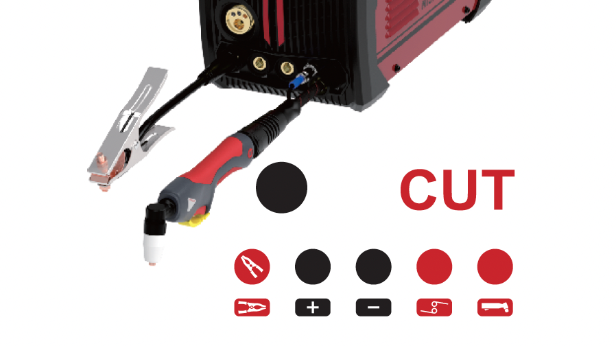
The ground clamp is plugged in the first Dinse socket; bottom left, where the ground clamp symbol is located. The torch has two connections next to each other on the bottom right on the front of the welder.
The brass connector on the torch lead threads over the port above the torch illustration, while the smaller electrical two-pin connection threads are next to it. Make sure you align the indentation on the electrical connection lead with the socket. Tighten both connections by hand, and everything is set.
Plasma Arc Start
To initiate the plasma arc, you need to press the trigger on the torch to release the air, come in contact with the metal, and lift the tip slightly. This will initiate the arc, and by dragging the torch, you will be slicing through metal.
Adjust your cutting speed to the thickness of the metal you are cutting. Thicker metals need a slower travel speed while thinner gauge is faster to cut.
The Plasma Cutter Settings
The plasma cutter menu lets you modify the cutting amperage output, air pre and post-flow duration, 2T/4T, and the stored memory settings.
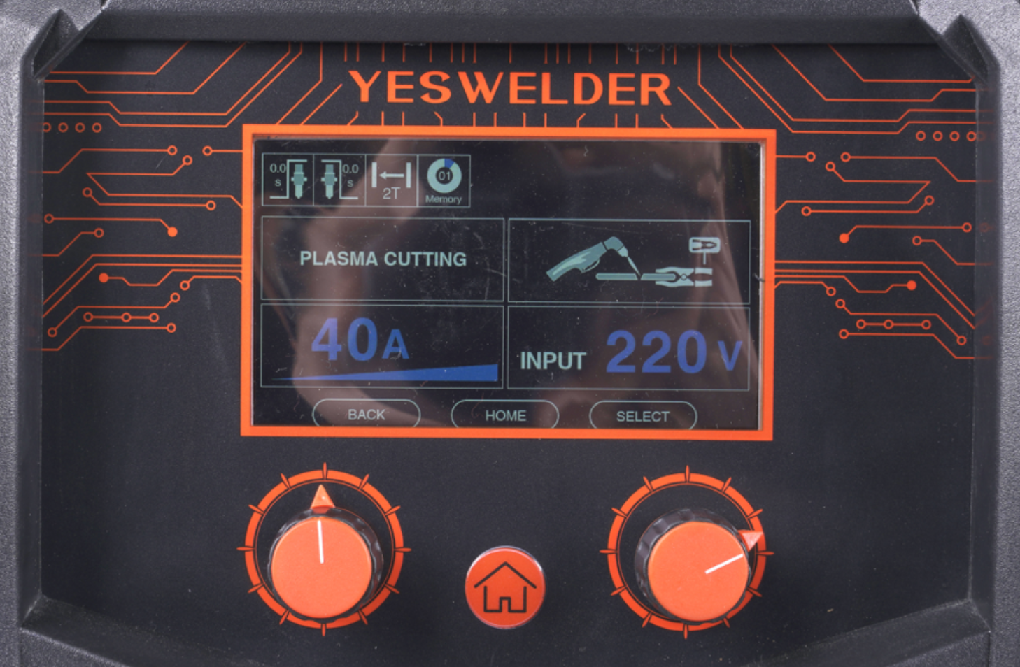
To change the amperage output, use the left knob, and to access the other settings, press the right knob. The pre and post-airflow adjustment lets you tailor how much air you wish to use to clean the area pre-cutting, and how much to cool the torch.
Conclusion
The Yeswelder Firstess MP200 is a versatile machine that's easy to operate thanks to the big display and intuitive menu. The included processes are easy to set up and run, but it's helpful to read a detailed guide for a complete beginner. Once you set up the welder yourself a few times, it will become second nature, and you'll be able to do it in a flash on any occasion.
Remember always to use safety equipment and abide by all safety codes and regulations in your area. If you are not sure about something safety-wise, it's always better to do a little research before you proceed with welding or cutting.
🧐 YesWelder MP200 5-in-1 Welder & Cutter FAQ
1. What processes does the YesWelder MP200 support?
The YesWelder MP200 supports MIG, self-shielded flux-core, DC Lift TIG, Stick welding, and plasma cutting. Its 5-in-1 design allows users to handle several welding and metal-cutting jobs with one machine.
2. Can the YesWelder MP200 run on both 110V and 220V?
Yes. The MP200 is a dual-voltage machine that can operate on 110V or 220V input power. Using 220V provides the full output needed for more demanding welding and plasma-cutting work.
3. Can the YesWelder MP200 weld aluminum?
No. The MP200 provides DC TIG and does not support the AC TIG output needed for conventional aluminum TIG welding. It also does not support an aluminum spool gun.
4. What polarity should I use with the YesWelder MP200?
Solid-wire MIG normally uses DCEP, while self-shielded flux-core welding and DC TIG use DCEN. Stick welding may use DCEP or DCEN depending on the electrode, so check the polarity listed on the electrode package.
5. What shielding gas does the MP200 use for MIG and TIG welding?
For MIG welding mild steel, use 75% argon and 25% CO2 or 100% CO2. For TIG welding mild steel or stainless steel, use 100% argon or a suitable argon and helium mixture.
6. What air compressor does the MP200 need for plasma cutting?
The MP200 requires an external air compressor capable of supplying approximately 9–12 CFM at 78 PSI. Set the working pressure within the recommended 58–72 PSI range and use only clean, dry compressed air.
4 comments


Great choice! And we have good news :) . It is now on sale for 15% off, you can get it for $849 only! Hurry while the supply last and the discount is still on. :) Here is a link for you – <https://yeswelder.com/collections/welder-cutter/products/firstess-mp200>
I went this how much!!
Pricing on 5-1 machine. Just love the yes whip on my Hobart, thanx pete
This is very helpful. Thank you!
Leave a comment